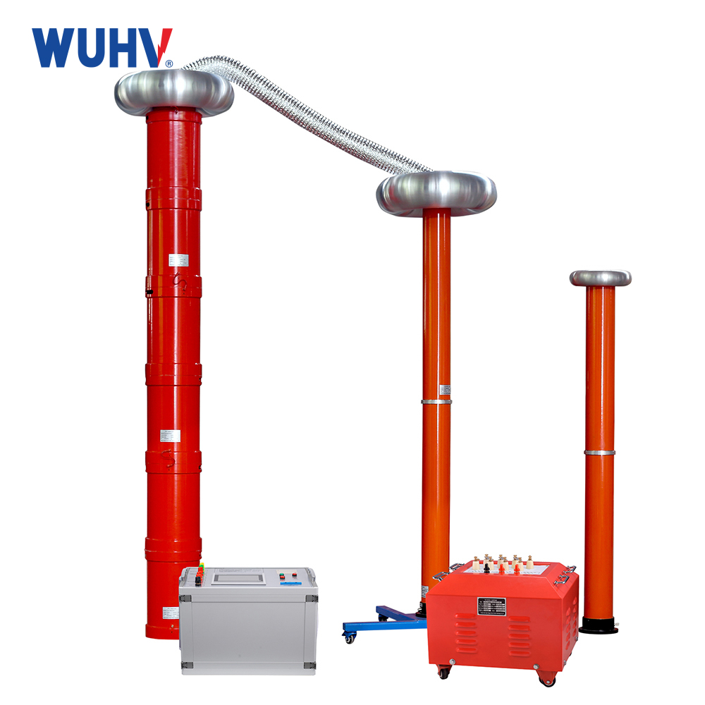
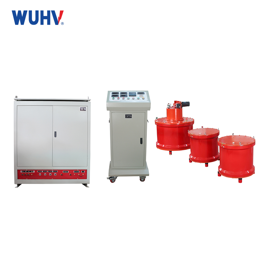
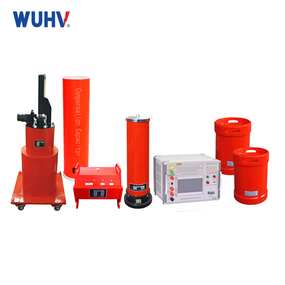
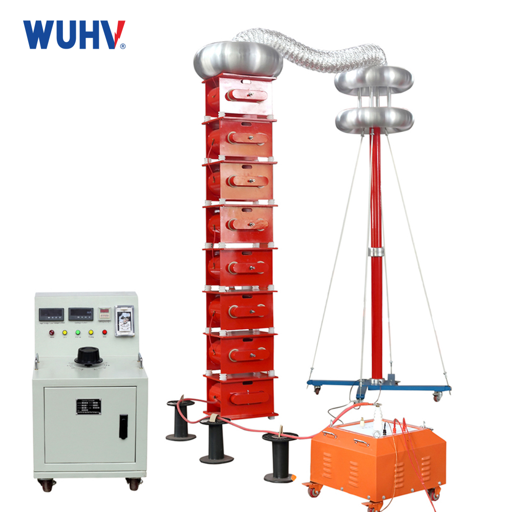
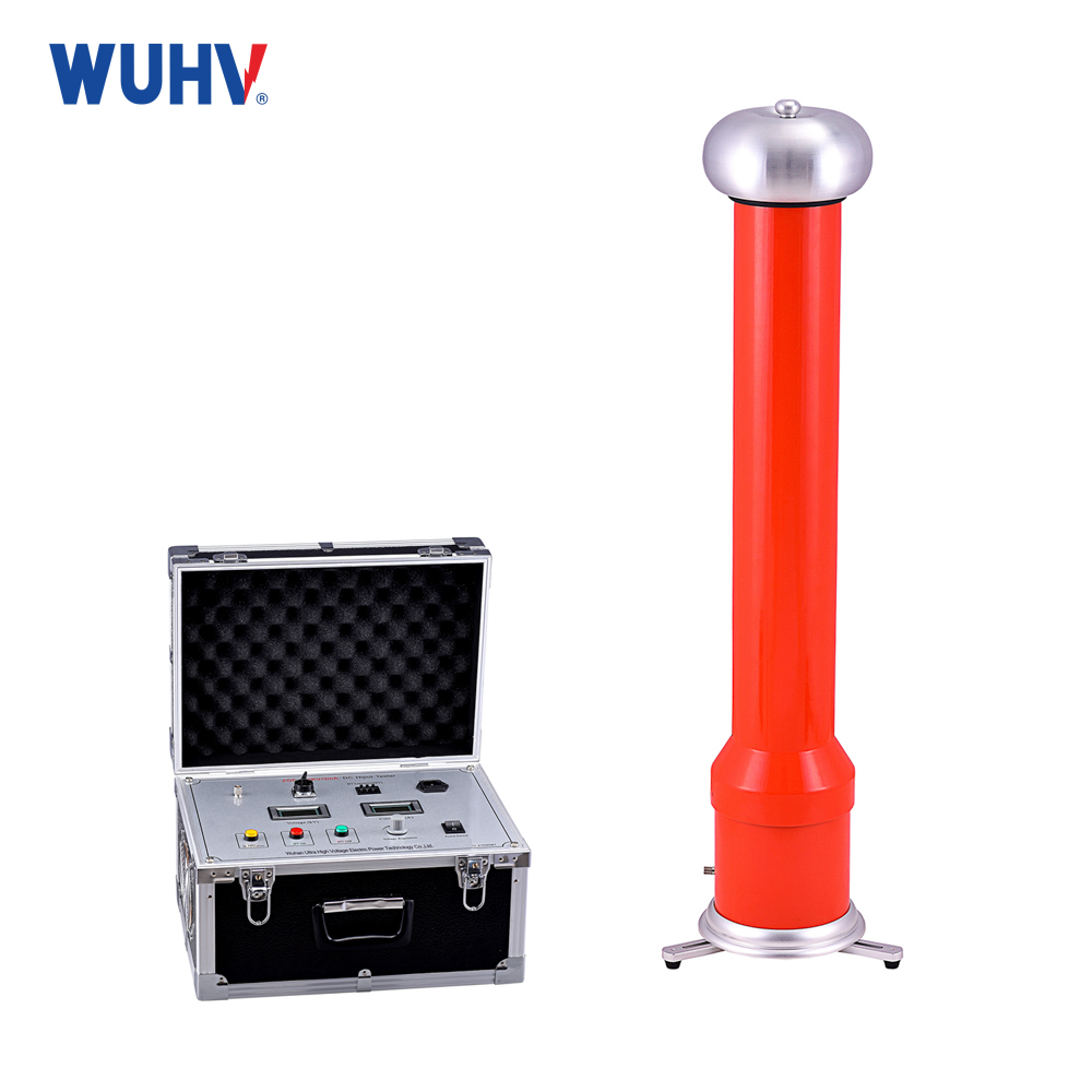
The Frequency Conversion AC Series Resonantunder UHV power can help many power workers conduct various power tests more conveniently.
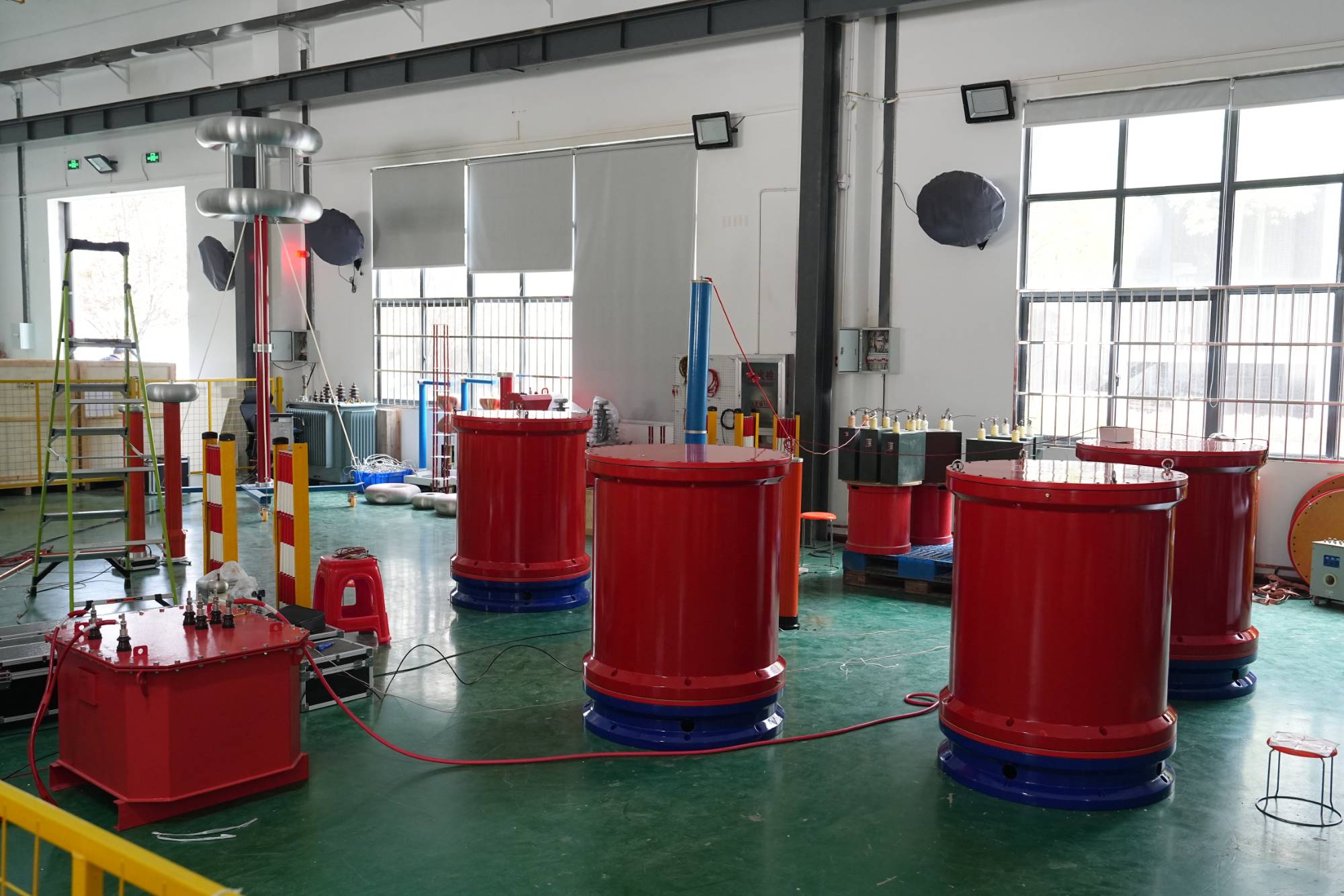
Q: What are the AC withstand voltage testing methods using the series parallel resonance principle?
Answer: For AC withstand voltage testing of large capacity test objects such as long cable lines, capacitors, large generators, transformers, etc., large capacity testing equipment and power sources are required, which are often difficult to achieve on site. In this case, series parallel resonance or series parallel resonance (also known as series parallel compensation) can be used according to the specific situation to solve the problem of insufficient capacity of the testing equipment.
(1) Series resonance (voltage resonance) method. When the rated voltage of the test transformer cannot meet the required test voltage, but the current can meet the test current of the tested object, the problem of insufficient test voltage can be solved by series resonance.
(2) Parallel resonance (current resonance) method. When the rated voltage of the test transformer can meet the requirements of the test voltage, but the current cannot reach the test current required by the tested object, parallel resonance compensation current can be used to solve the problem of insufficient capacity of the test power supply.
(3) Series parallel resonance method. In addition to the series parallel resonance mentioned above, when the rated voltage and rated current of the test transformer cannot meet the test requirements, a series parallel resonance circuit, also known as series parallel compensation method, can be used simultaneously.
Q: What are the conditions for voltage resonance? What are the conditions for current resonance?
Answer: In a circuit composed of an inductor coil (which can be simulated by connecting inductor L in series with resistor R) and a capacitor element (capacitor C) in series, voltage resonance occurs when the inductance and capacitance are equal. In depth analysis is as follows:
(1) When l and C are constants, the frequency f of the power supply is exactly equal to the natural oscillation frequency of the circuit, that is, f=1/(2 π√ LC).
(2) When the power frequency is constant, adjust the inductance L so that l=1/[(2 π f) 2C].
(3) When the power frequency is constant, adjust the capacitor C to make C=1/[(2 π f) 2L]. In a circuit composed of an inductor coil (which can be simulated by inductor L in series with resistor R) and a capacitor element (capacitor C) connected in parallel, current resonance will occur if one of the following conditions is met.
(1) Power frequency f=1/2 π√ 1/lc-r/L
(2) Adjust the capacitor to make C=L/[R2+(2 π FL) 2]
(3) When 2 π FCR ≤ 1, adjusting inductance L may also cause current resonance.
Q: What are the methods for the series resonant withstand voltage test of transformers?
Answer: There are two common methods for series resonant withstand voltage testing of transformers:
(1) Inductive series resonant withstand voltage test. The adjustable inductor L is connected in series in a high-voltage circuit. When adjusting the reactor to WL1/WCX=, the voltage drop across the reactor is numerically equal to the voltage drop across the capacitor, and the circuit reaches a resonant state, generating a high frequency voltage on the measured object.
(2) Variable frequency series resonance withstand voltage test. When the frequency converter is connected to the test power supply, the power frequency can be adjusted within 30-300hz. When the output voltage frequency of the frequency converter cabinet reaches the resonance condition, that is, f=1/(2 π√ LC), a resonant high voltage will be generated on the test object. If the reactor combination and capacitance are adjusted simultaneously, the test frequency can be controlled within the frequency range of 45-65fhz, and most can be controlled within the frequency range of 49-51 hz. Due to the convenience of adjusting the equipment to reach the vibration free point, it is currently widely used on site.
Q: What are the precautions for transformer series resonance withstand voltage test?
Answer: When conducting a series resonant withstand voltage test on transformers, attention should be paid to:
(1) Tuning should be performed before boosting. When using a series resonance test device, the test voltage frequency shall not be lower than 40Hz, and the full voltage withstand time shall be 60s. During the experiment, the inductance or frequency should be tuned under low excitation voltage to find the resonance point. When the voltage on the test object reaches its highest point, which is the resonance point of the test circuit, the boost test can begin.
(2) The quality factor Q value of the resonant testing circuit is related to the dryness and cleanliness of the testing equipment and the insulation surface of the testing object, as well as the diameter and length of the high-voltage leads. Therefore, the test should be conducted on clear weather. The insulation surfaces of testing equipment and test objects should be dry and clean. Try to shorten the length of high-voltage leads as much as possible and use large-diameter high-voltage leads to reduce corona losses. Improve the quality factor Q value of the testing circuit.
Q: What are the possible reasons for insulation failure of power equipment in withstand voltage testing?
Answer: During the withstand voltage test, the possible reasons for the insulation failure of power equipment include:
(1) Insulation degradation. For example, moisture in transformer oil, moisture in solid insulation, insulation aging, etc. can all lead to a decrease in insulation performance and may fail the withstand voltage test.
(2) The testing method and voltage measurement method are incorrect. For example, during transformer testing, if the untested winding does not have a short circuit to ground, the untested winding may discharge to ground and be misjudged as unqualified. For example, when testing large capacity test objects, the voltage is still measured on the low voltage side. Due to the rising effect of capacitance, the actual voltage applied to the tested object exceeds the test voltage, resulting in breakdown of the tested object and misjudgment as unqualified.
(3) Without proper consideration of atmospheric conditions that affect insulation properties. Due to the influence of air pressure, temperature, and humidity on spark discharge voltage and breakdown voltage, if these factors are not considered, it may be concluded that the equipment is unqualified.


