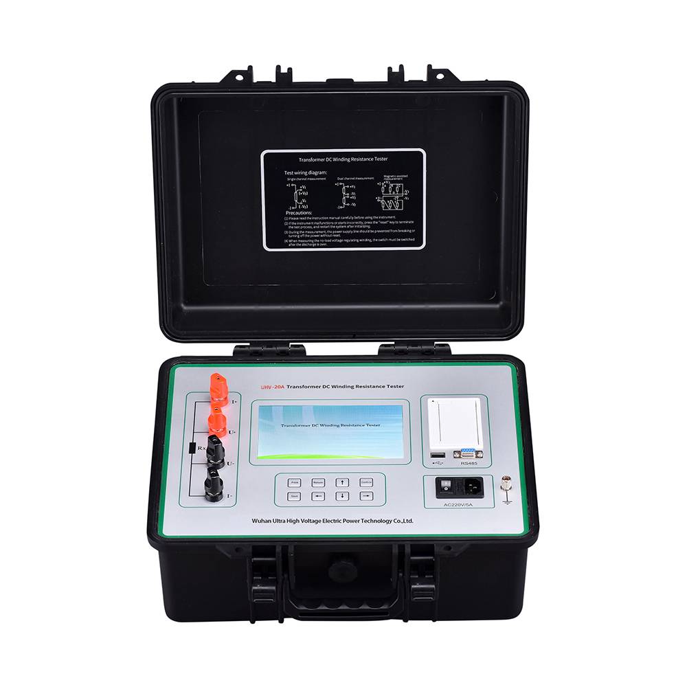
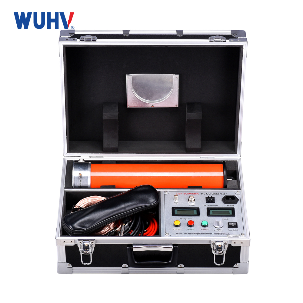
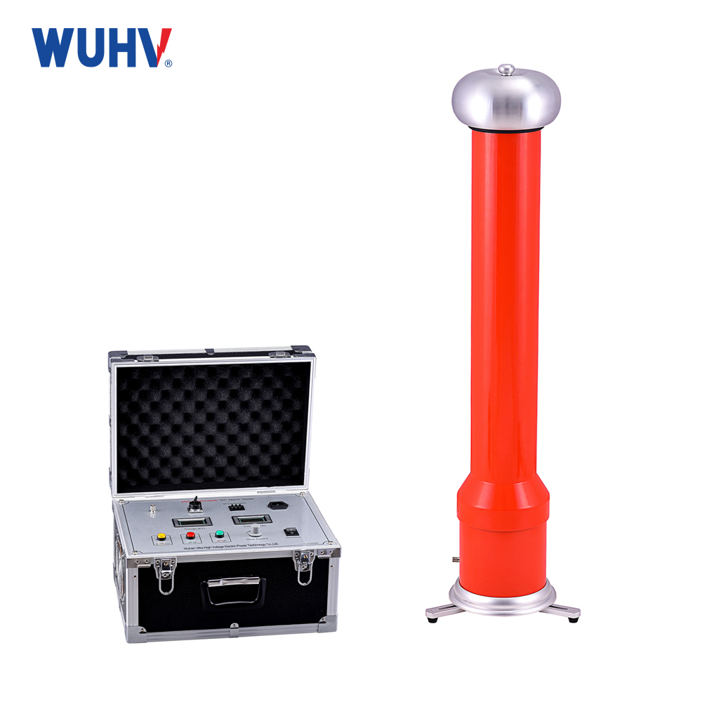
The DC resistance testerunder UHV power can help many power workers conduct various power tests more conveniently.
1. When measuring the DC resistance of a transformer, due to the large inductance, it is necessary to charge it properly and minimize the self inductance effect. After the pointer of the DC resistance tester stabilizes, read the resistance value to improve accuracy and precision.
2. The results of the DC resistance tester should be compared horizontally and vertically, and the influencing factors such as temperature, phase difference, wiring method, tap changer, poor contact, and disconnection should be fully analyzed.
a. Temperature influence
DC resistance is directly proportional to temperature. The DC resistance varies at different oil temperatures. The DC resistance measured at different temperatures should be converted to the same temperature for comparison purposes. The formula for converting DC resistance temperature is:
R2=R1(T+t2)/(T+t1)
(Where R1 and R2 are the resistance values at t1 and t2 temperatures, respectively, T is the resistance temperature constant, and the copper wire is 235)
b. The impact of phase difference
The calculation of the percentage difference or phase difference between DC resistance lines can be carried out as follows:
△Rx=(Rnax-Rmin)/Rp
(Δ Rx is the percentage of DC resistance line difference or phase difference, Rmax is the maximum value of three wire or three-phase DC resistance measurement, Rmin is the minimum value of three wire or three-phase DC resistance measurement, Rp is the average value of three wire or three-phase (DC resistance measurement))
c. The impact of wiring methods
The three-phase winding of the transformer is Y connected or connected. If the unbalanced value of the three-phase line resistance exceeds the standard, the line resistance must be converted to phase resistance in order to detect the faulty phase.
d. The impact of tap changers
The measurement result is incorrect during the process of measuring the on load tap changer transformer. Firstly, check the DC resistance at all tap positions to see if it is caused by poor contact of the polarity switch or loose leads.
e. Poor contact
If the conductive rod in the transformer bushing has poor contact with the internal leads, causing the joint to heat up, infrared imaging can be used to analyze the heating part.
f. The impact of disconnection
If one phase of the transformer winding with a delta connection is disconnected, the resistance value of the two terminals that are not disconnected is 1.5 times the normal value, and the resistance value of the disconnected phase terminals is 3 times the normal value.
3. To determine the results of a DC resistance tester, it is necessary to comprehensively consider relevant factors and standards, and analyze in detail the development and changes of equipment measurement data.
4. The judgment of the results of the DC resistance tester emphasizes the analysis, judgment, and verification of comprehensive methods.


