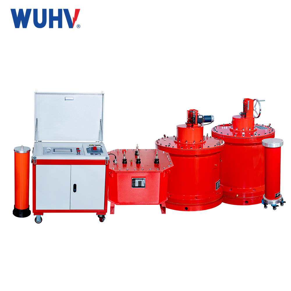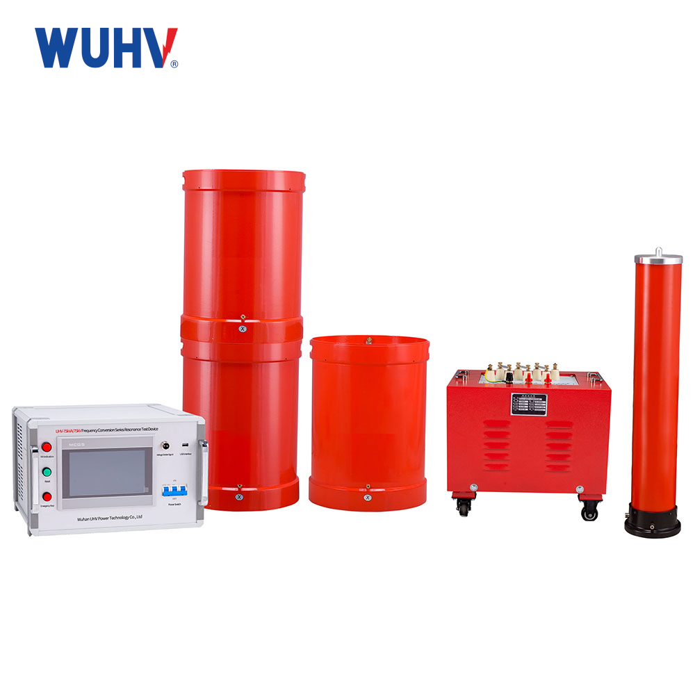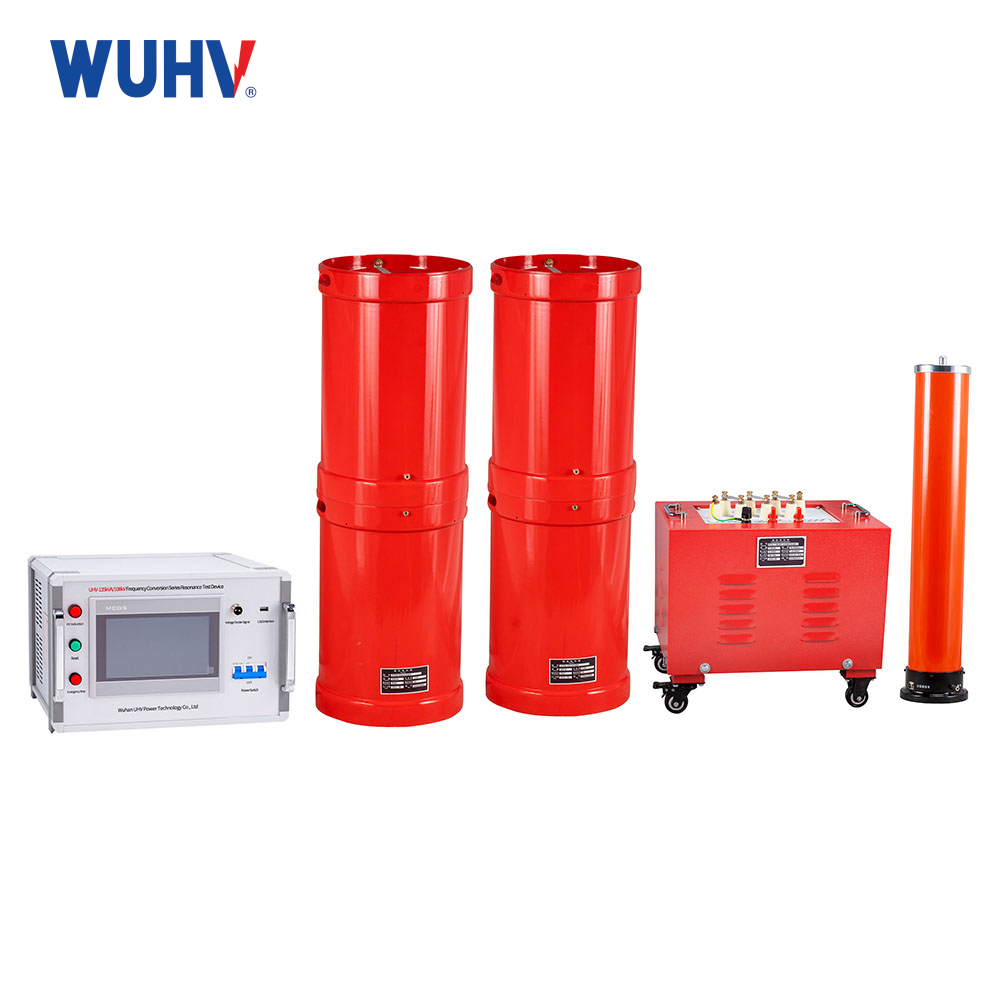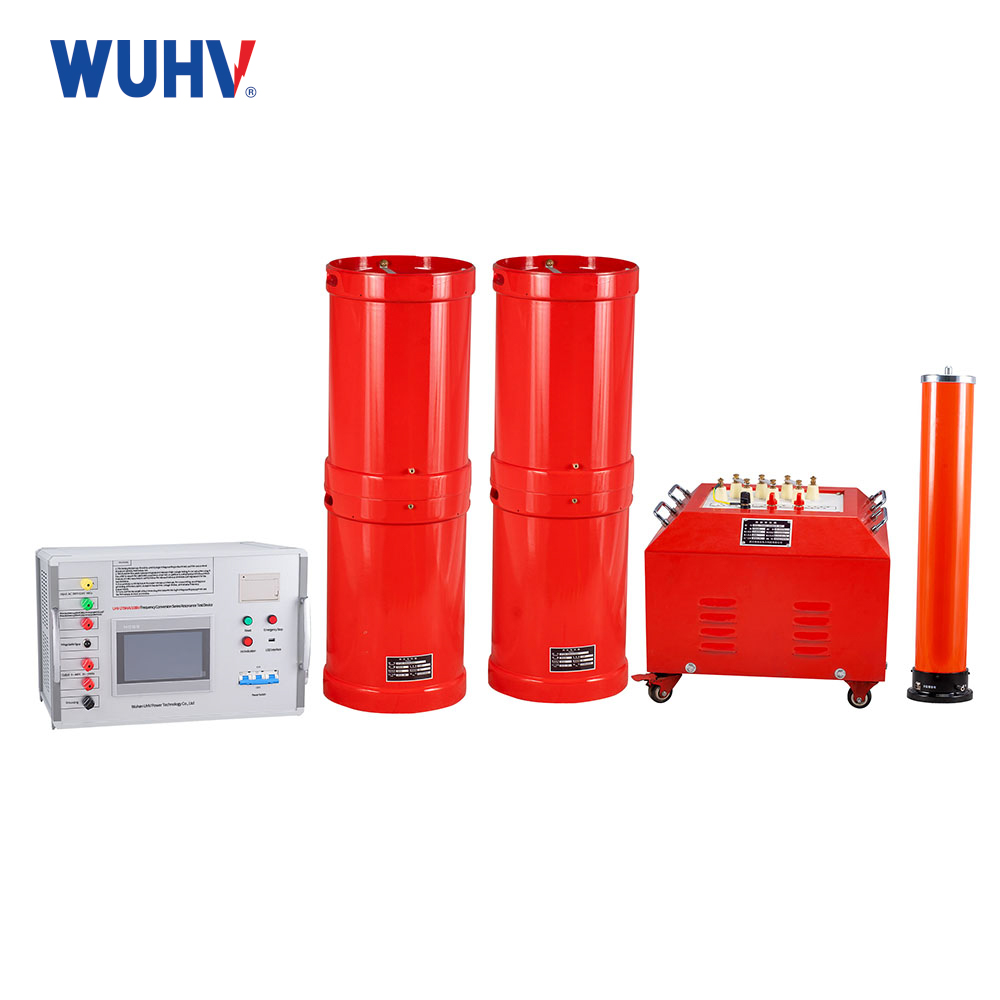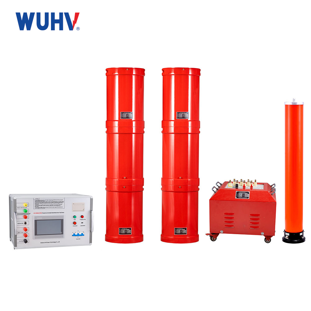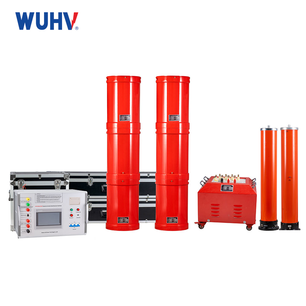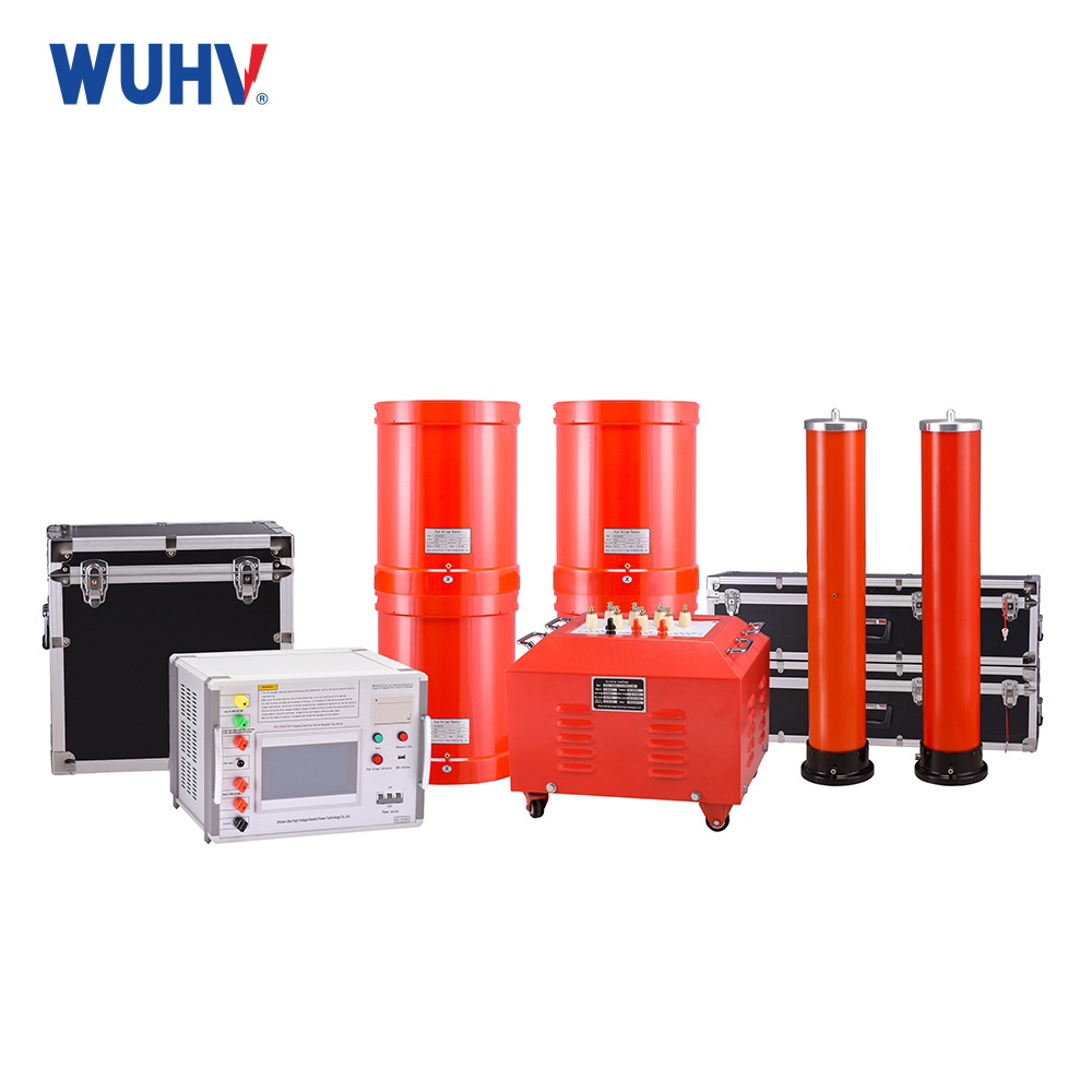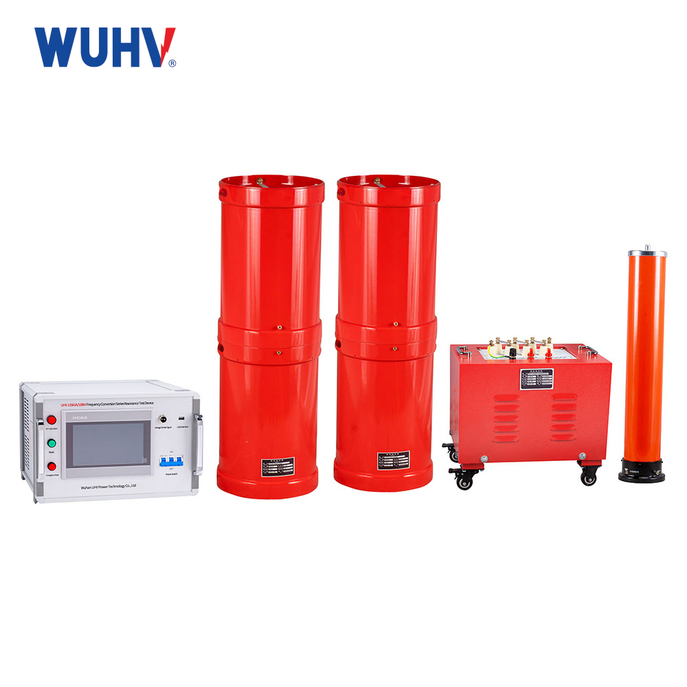
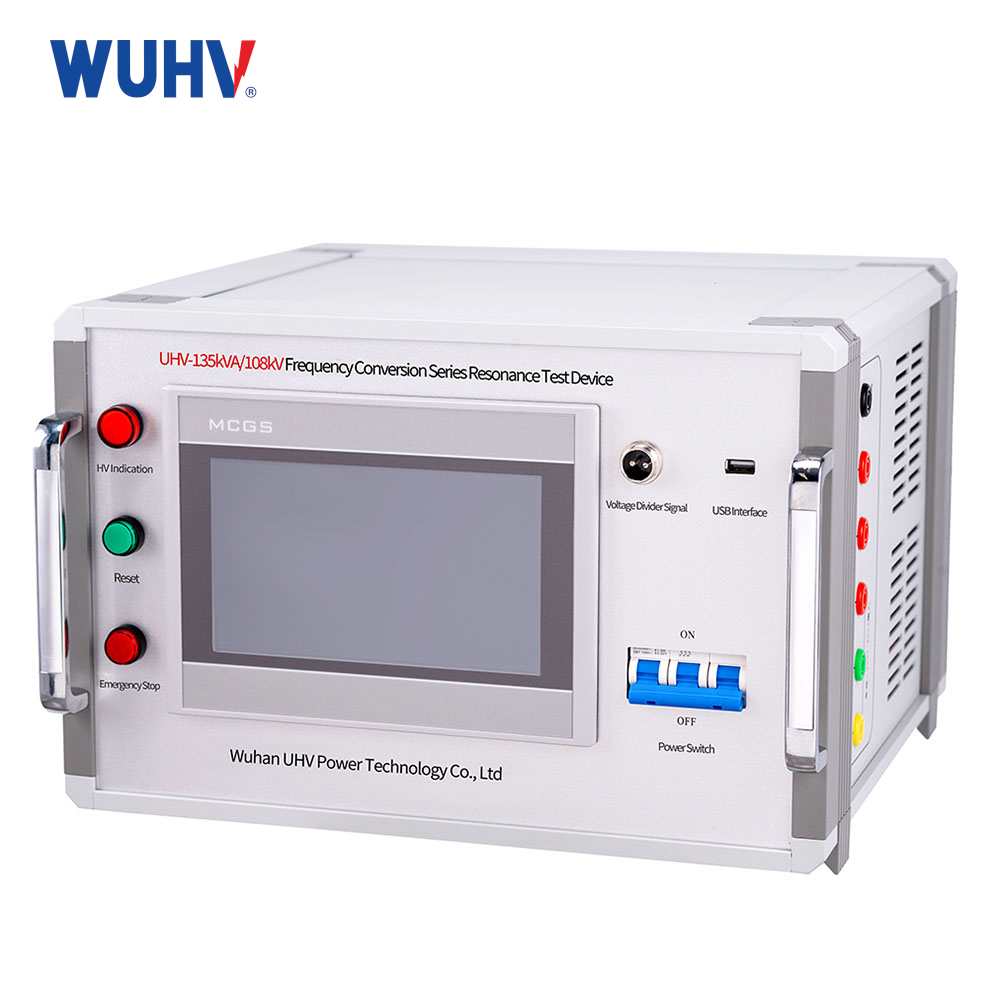
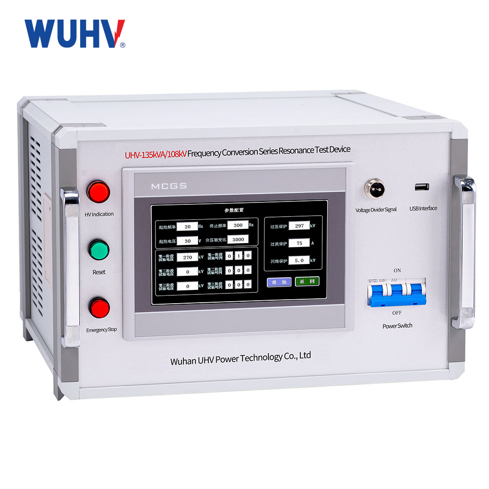
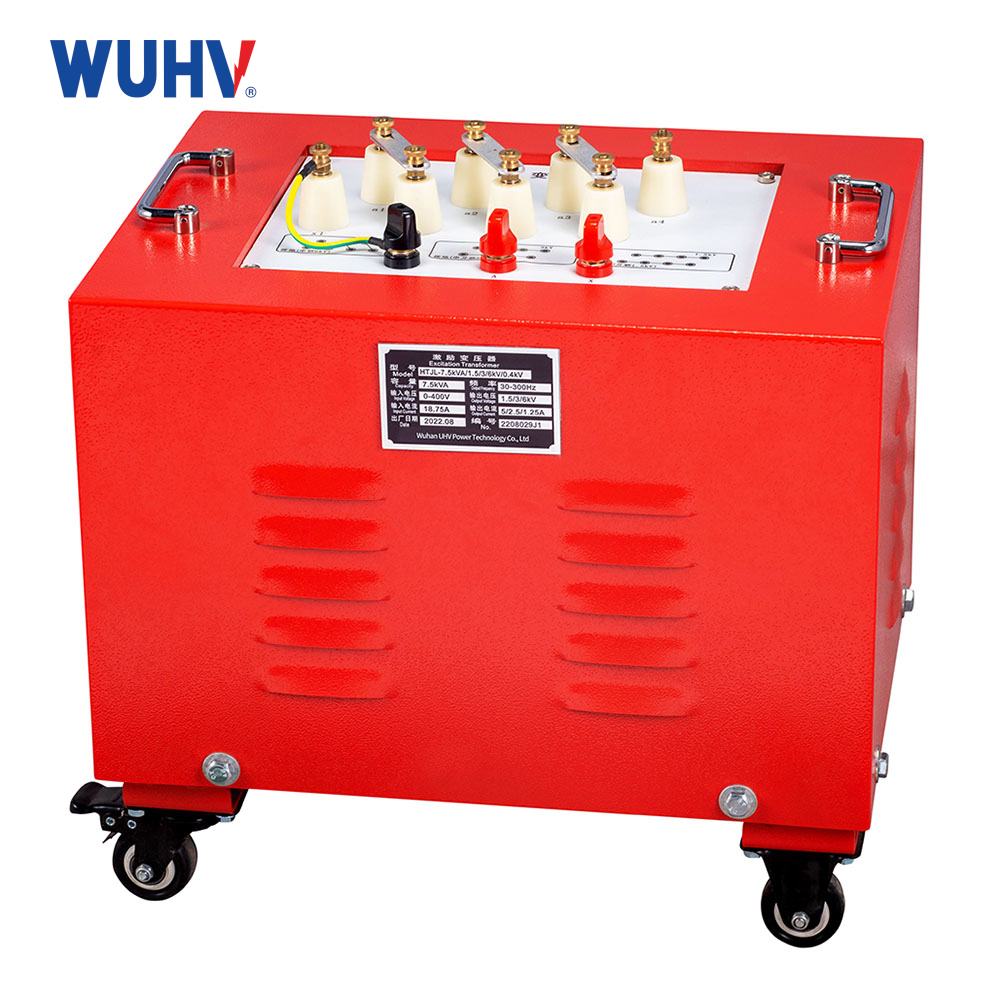
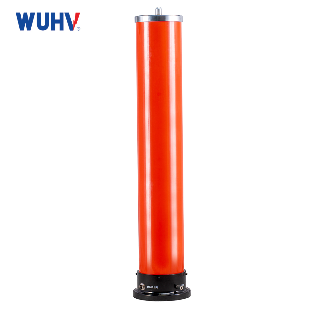


Кабельге арналған UHV-135 кВА/108 кВ резонанстық сынақ жинағы
 Өнімге кіріспе
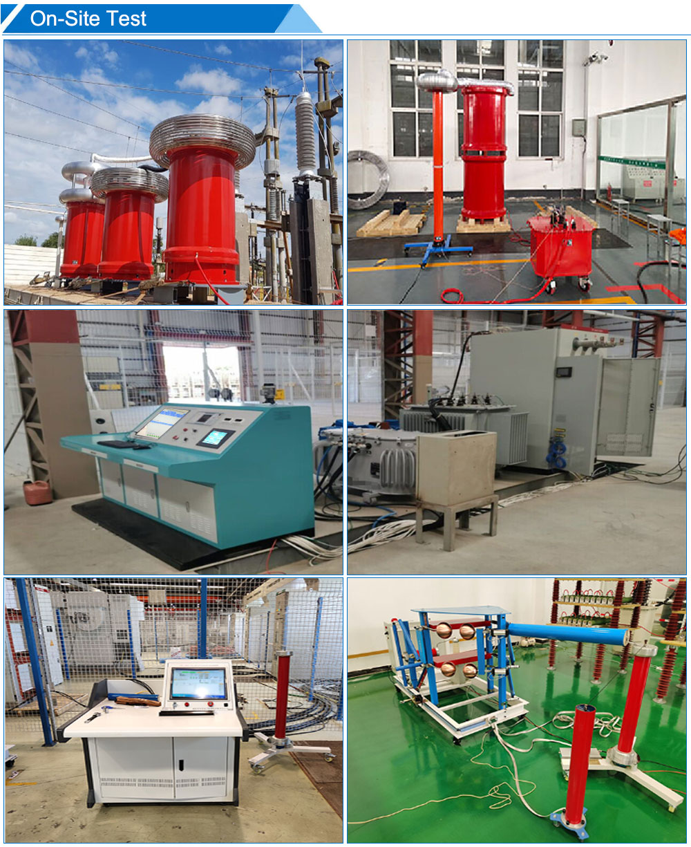
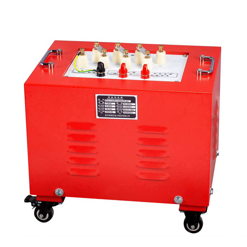
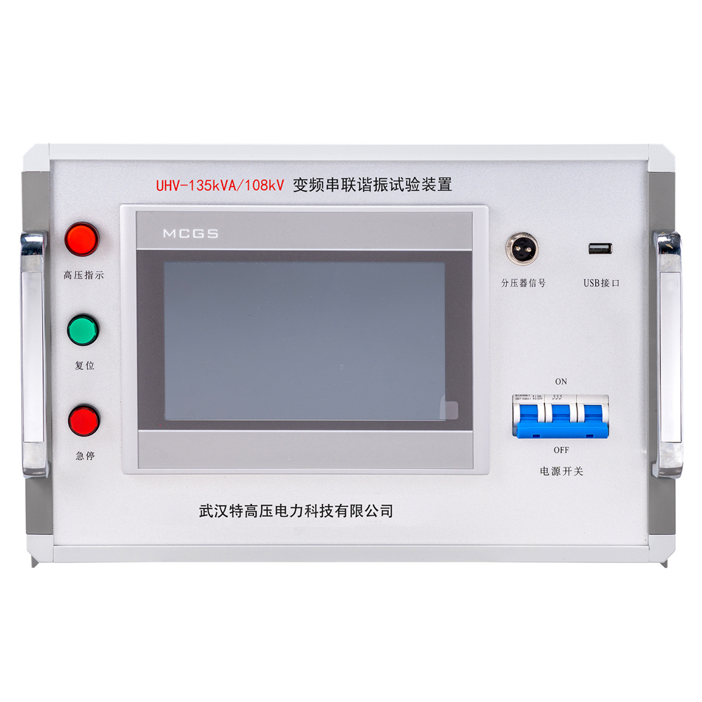
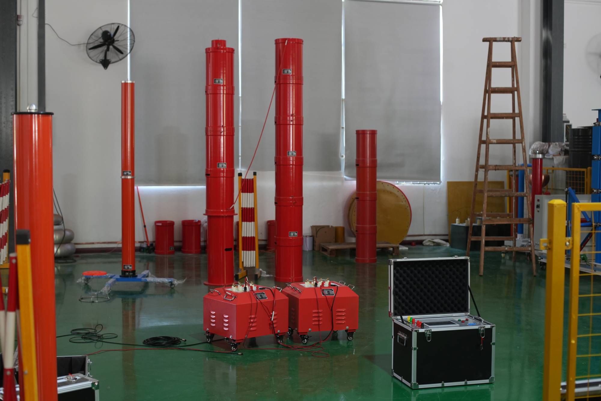
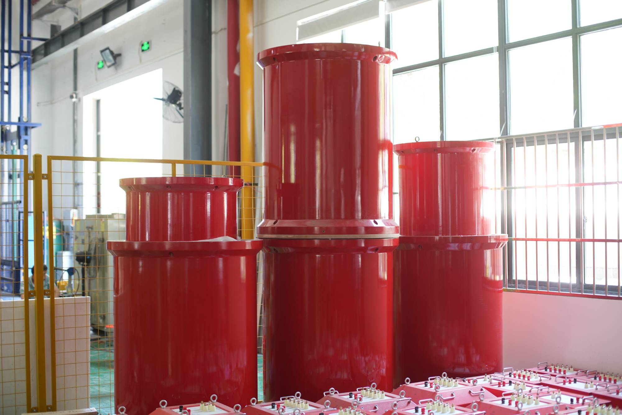
The UHV-135kVA/108kV series resonance system manufactures adopts the method of adjusting the power supply frequency to achieve resonance between the reactor and the test capacitor, thereby obtaining high voltage and large current on the test object. Due to its small required power supply, light weight, and compact size, series resonant test equipment has received widespread acclaim and application both domestically and internationally. resonant test set for cable represents a new method and trend in high-voltage testing.
Негізгі техникалық параметрлер мен функциялар
Номиналды қуаты: 135 кВА
Номиналды кернеу: 27 кВ ;54 кВ ;108 кВ
Номиналды ток: 5A ;2.5A ;1.25A
Өлшеу дәлдігі: Жүйелік RMS деңгейі 1.5
Жұмыс жиілігі: 30-300 Гц
Құрылғының шығыс толқын формасы: Синусоидалы толқын
Сапа факторы: Құрылғы Q≥30(f=45Гц)
Толқын пішінінің бұрмалану жылдамдығы: Шығыс кернеуінің толқын пішінінің бұрмалануы ≤1%
Кіріс қуат көзі: бір фазалы 220 немесе үш фазалы 380 В кернеу, жиілігі 50 Гц
Жұмыс уақыты: Номиналды жүктеме кезінде үздіксіз 60 минутқа рұқсат етіңіз; Шамадан тыс қысым 1,1 рет 1 минут
Температураның көтерілуі: Номиналды жүктеме астында 60 минут бойы үздіксіз жұмыс істегеннен кейін температураның көтерілуі ≤65K
Қорғаныс функциясы: шамадан тыс кернеу, шамадан тыс ток, нөлдік іске қосу, жүйенің сәйкес келмеуі (флэш-овер) және басқа қорғаныс функциялары
Қоршаған орта температурасы: -20℃ -55℃
Салыстырмалы ылғалдылық: ≤90% RH
Биіктік: ≤3000 м
Meet the test range
1, AC withstand voltage test for 10kV/300mm² cable of 3km, capacitance ≤1.1265μF, test frequency 30-300Hz, test voltage 22kV, test duration 5 minutes.
2, AC withstand voltage test for 10kV switch and other substation equipment, test frequency 30-300Hz, test voltage not exceeding 42kV, test duration 1 minute.
3, AC withstand voltage test for 35kV/300mm² cable of 1km, capacitance ≤0.1945μF, test frequency 30-300Hz, test voltage 52kV, test duration 60 minutes.
4, AC withstand voltage test for 35kV/31500kVA main transformer, capacitance ≤0.02μF, test frequency 45-65Hz, test voltage 68kV, test duration 1 minute.
5, AC withstand voltage test for 35kV switch and other electrical equipment, test frequency 30-300Hz, test voltage not exceeding 95kV, test duration 1 minute.
 |  |
Comparison between series resonance and VLF High Voltage Generator (0.1 Hz VLF)
1. Equivalence and test standards:
The series resonant frequency is close to power frequency (50 Hz), so its breakdown effects are fully consistent with actual operating conditions, making it the most authoritative test method. VLF, with its extremely low frequency, has a high detection rate for water‑tree defects in XLPE cables, but strictly speaking it is not an "equivalent power‑frequency" test; in some situations it can only serve as a "preliminary test".
2. Size and weight (minor differences):
Series resonance requires reactors and an excitation transformer. At lower voltage levels, the two systems are similar in size. However, at very high voltages (e.g., above 220 kV), VLF equipment, due to its voltage‑doubler rectifier structure, can be slightly more compact than a series resonant set.
3. Test duration:
Series resonant withstand test device factory takes only a few seconds to a few minutes. In contrast, a VLF test (0.1 Hz means one cycle takes 10 seconds) must typically run for 15–60 minutes as per regulations – it is extremely time‑consuming.
Core functional characteristics of variable frequency series resonant device:
Extremely low power demand: By utilizing the voltage doubling effect, the required power capacity is only 1/Q of the output capacity and can be driven by a small generator.
Automatic frequency scanning and tuning: One click start, automatic scanning and locking of resonant frequency (accuracy up to 0.1Hz), no need for manual adjustment.
Pure output waveform: The LC circuit comes with filtering function, and the distortion rate of the output sine wave is extremely low.
Breakdown self-protection (soft characteristic): When the test sample breaks down, resonance is immediately destroyed, the current automatically drops sharply, and the arc extinguishes automatically, without causing secondary expansion damage to the test sample and equipment.
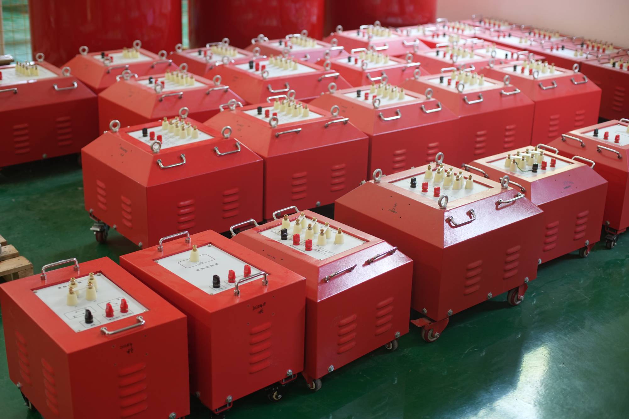
Reactive power compensation capability: using reactors and inductors to offset the capacitance current of the test sample, the power supply only provides active power for resistance losses, especially suitable for large capacitive loads such as long cables.
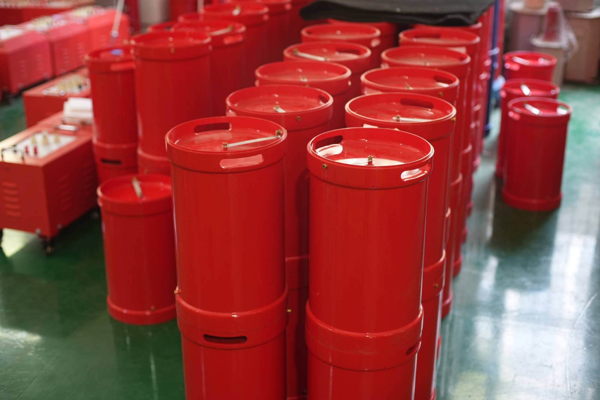
Modular combination: The reactor can be combined in series/parallel with multiple sections, flexibly matching different voltage levels and sample capacities.
 |  |
Main application scenarios
Its main service target is large capacitive power equipment:
Long distance power cables: AC withstand voltage test of cross-linked polyethylene (XLPE) cables (currently the most important application).
GIS (Gas Insulated Switchgear): Due to its small capacitance but extremely high voltage, reactors are often used in series to boost the voltage.
Large generators/transformers: Conduct AC withstand voltage assessment at the output terminal or overall.
Preventive testing of indoor/outdoor equipment such as high-voltage switches, transformers, insulators, etc.
Core Questions on “Selection & Matching”
Q: My test objects are mixed (cables, GIS, transformers). Can one set handle all of them?
A: Yes, but not with a single fixed configuration. series resonant systems are custom‑built; the key lies in reactor combinations.
Cables – large capacitive loads → need high current, low inductance reactors (multiple units in parallel).
GIS/switches – small capacitive loads → need high voltage, low current reactors (multiple units in series).
Transformers/motors – inductive loads → require compensation capacitors to achieve resonance.